![]()
![]()
![]()
![]()
|
|
|
|
|
>>> View: Logger Control [Channel and Probe Setup]
>>> Ctrl L [Channel and Probe Setup]
>>> ![]() [Channel and Probe Setup]
[Channel and Probe Setup]
This tab allows the user to specify what probes have been connected to a certain logger. If the logger has inputs that have dedicated probes attached then the software will not allow these to be changed. (See Channel and Probe Setup Overview)
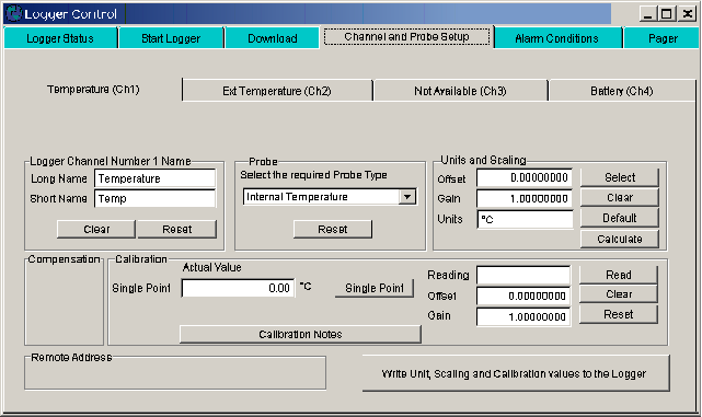
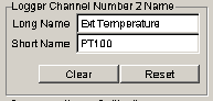
Logger Channel Name
This area is used to specify the names used to identify the probe connected to that channel
Long Name
Specifies a long name used to identify the probe up to 16 characters are allowed
Short name
Specifies a short name used to identify the probe up to 6 characters are allowed
Clear names
Clears the long and short name fields
Reset names
Resets the name fields back to the last used names.
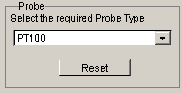
Probe selection
Selects which probe has been connected to this input.
Select probe
Allows the user to select a probe that is compatible with that input. Some loggers have fixed probes and this will only show the one option.
Reset probe selection
Resets the probe type to the last probe used on this channel
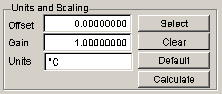
Units and scaling
Used to set up the units that are available for the selected probe.
Offset
Allows the offset to be entered for probes that do not have a standard units
Gain
Allows the gain to be entered for probes that do not have a standard units
Units
Allows the units to be entered. Up to 6 characters. This is automatically filled in for standard units
Select units
Used to select the units for the probe from a standard set.
Clear units
Clears the offset, gain and units to 0,1 and blank.
Default units
Sets the offset, gain and units to 0,1 and The S.I. units.
Compensation
Used to set the compensation channels if required for the probe specified.
Some probes like the humidity probe needs to use the temperature probe that is mounted with it to temperature compensated the humidity value. The channel or channels to be used for this are specified here. Setting the number to 0 disables compensation.
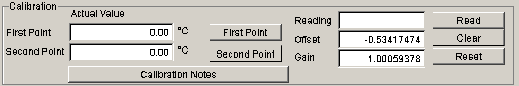
This area is used to calibrate the connected probe. Some probes do not need calibration, some need one point, some need two point calibration. This area will change depending on the type needed.
Calibration Notes
Calibration notes on the different probe types are available in this help file. The notes for the selected probe can be viewed using the Calibration Notes button.
Actual Value First Point
Enter into this area the actual value of the calibration cell the probe is in
Actual Value Second Point
If doing two point calibration this is the value of the cell used for the second point. The first point must always be set first.
First point button
Press this button after entering the value into the actual value first pint area and the probe has stabilized to the reference cell.
Second point button
Press this button after entering the value into the actual value second point area and the probe has stabilized to the second reference cell.
Reading calibration
Displays the reading obtained from the logger when either the first or second point buttons are clicked. Used as a fault finding tool.
Offset calibration
This is the calculated offset from the calibration. Some probes may be supplied with a calibration certificate with this value on it. If so just enter the value here.
Gain Calibration
This is the calculated gain from the calibration. Some probes may be supplied with a calibration certificate with this value on it. If so just enter the value here.
Read Calibration
Reads the current logger probe and displays the reading in the Readings window
Clear calibration
Clears the calibration to
Reset Calibration
Resets the calibration to the last value saved to the logger
![]()
Write unit, scale and calibration values from the logger
Writes the units, scale and calibration values to the currently connected logger