![]()
|
|
|
Setting up the Soil Moisture Tension Probe and Logger
![]()
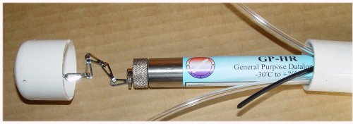
The Soil Moisture Tension probe is usually supplied with a GP-HR (General Purpose High Resolution Logger). The probe and logger have been calibrate together so it is important to keep the logger with the probe that it has been calibrated with. Sometimes the probe and logger will be supplied already connected together. If probes and loggers are supplied separately the probes and loggers will be numbered so that the the correct probe can be connected to each logger.
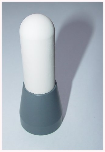
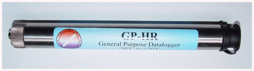
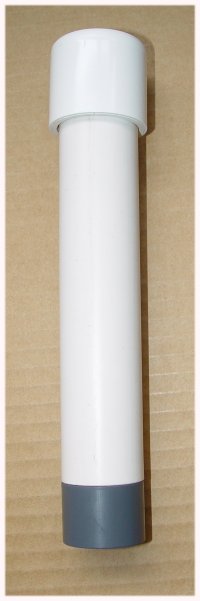
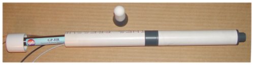
Before starting the setup procedure, identify the following parts.
| Ceramic Cup attached to screw-on collar. This is usually supplied separately so that the ceramic cups can be packed specially during transport. |
|
| Soil Moisture Tension Pressure Sensor. This contains the pressure sensor and electronics, the water reservoir, the air breather tube (Black), two water filler tubes (Clear) and the cable to the logger with 6pin plug. |
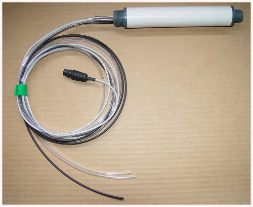 |
| GP-HR Data Logger. This has a 6pin switchcraft socket for connection to the Sensor, at one end and a 3pin communication socket at the other end for connection to a computer. The communication socket is protected by a screw on cap. |
|
| Cable Protection Tube with Cap and logger
suspension chain. The tube runs from the sensor up to the surface of the soil. It protects the cables and tubes that run down to the sensor. The logger can be suspended from the chain attached to the white plastic cap at the top of this tube.This tube is supplied in lengths as specified and can be cut to length, on site, as required. |
|
| The sensors are sometimes supplied with the Cable Protection Tube already connected to the Soil Moisture Sensor and the GP-HR logger already connected to the sensor and housed in the top of the Cable Protection Tube already connected to the suspension chain. |
|
![]()
Setting up the Sensor
The Ceramic Cup is screwed to the Sensor using thread seal (plumbing) tape on the screw thread to insure an air tight and water tight connection.
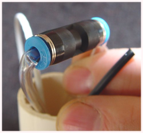
The Sensor with cup is fitted to the Cable Protection Tube using thread seal (plumbing) tape ensuring that the breather tube (black), Water filler tubes (clear) and logger connection cable are running up through the length of the cable Protection Tube.
Mount the Sensor and Cable Protection Tube upright with the ceramic cup pointing downwards.
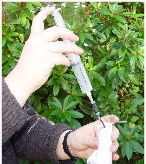
Open the water filler tubes (clear) by removing the joiner from one tube. There is a collar at each end of the joiner. Pushing inwards on the collar will release the tube from the joiner and it can then be withdrawn. Force water into the filler tube that still has the joiner attached until the reservoir is filled and water comes out of the second filler tube. This is most easily done using a large hypodermic syringe (not provided). Ensure that this water does not flow back into the Cable Protection Tube. Gently knock the side of the sensor as it is filled to dislodge any air bubbles adhering to the sides of the reservoir. Seal the filler tubes again with the joiner provided ensuring that no air bubbles are present in the filler tubes. The Sensor is now ready for positioning in the soil
![]()
Setting up the Logger
Install the Omnilog Software on the computer to be used to control the logger
Connect the Logger to a computer using a DLC3 Download Cable
Run the Omnilog Software and ensure the Logger is communicating with the Computer
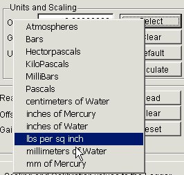
The Logger has been calibrated and is normally supplied with the pressure sensor reading hectaPascals (hPa). To change this:
go to the Logger Control Screen
Select the Channel and Probe Setup Tab
Select Pressure (Ch2) Tab
Do not change the Calibration Offset or GainIf soil moisture readings are required in Pounds per Square Inch (psi)
In the Units and Scaling Box
Click on the Select Button
Select lbs per sq inch
click the "Write Unit Scaling and Calibration values to the Logger" button
The Soil Moisture Sensor is now reading in psi
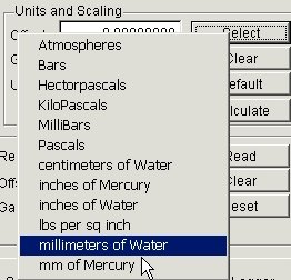
If soil moisture readings are required in mm of Water
In the Units and Scaling Box
Click on the Select Button
Select mm of Water
click the "Write Unit Scaling and Calibration values to the Logger" button
The Soil Moisture Sensor is now reading in mmH˛O
If soil moisture readings are required in percentage Available Water for a given soil type
Take a note of the Calibration Offset and Calibration Gain
These will be required if you want to reset the sensor to read in pressure in the future
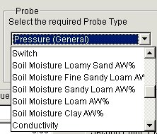
In the Probe Box
Click on the "Select the Required Probe Type" pull down list
Set the Probe to one of the following:
Soil Moisture Loamy Sand AW%
Soil Moisture Fine Sandy Loam AW%
Soil Moisture Sandy Loam AW%
Soil Moisture Loam AW%
Soil Moisture Clay AW%
click the "Write Unit Scaling and Calibration values to the Logger" button
The Soil Moisture Sensor is now reading in percentage available water for the soil type selected
The Logger is now setup to read the required Units
![]()
Starting the logger
this can be done in the lab or on site
connect the logger to a computer running the Omnilog software
go to the Logger Control Screen
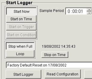
select the "Start Logger" Tab
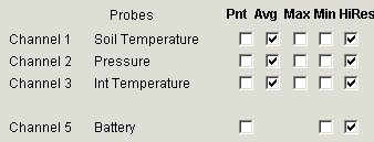
select the channels and modes to be logged in the panel to the right of the screen
select the required logging sample period in the panel to the left of the screen
click on the "Start Logger" button
The Logger is now running
![]()
Servicing the sensor and logger in the field
Remove the white plastic cap from the top of the Cable Protection Tube
raise the GP-HR up out of the tube using the chain attached to the cap
remove the logger cap to reveal the communication socket
connect the DLC3 download cable between the logger and computer (laptop)
Download the Data and Restart the logger if required
Use the Realtime screen to check the proper operation of the sensor
disconnect the download cable from the logger and replace the logger cap
refill the water reservoir as described above if required
check that there are no visible signs of moisture entering the cable protection tube
lower the logger back into the cable protection tube and replace the white plastic cap
![]()